
1、 Project background
China is a country with many mountains and rivers. Rivers and lakes are densely distributed, especially small and medium-sized rivers. Such a large number of rivers are easy to cause flood disasters. In order to prevent flood disasters, great efforts have been made to build reservoirs. The reservoir brings convenience to people, but it also has huge security problems. The reservoir has huge storage capacity, which is very easy to cause dam break in case of rainstorm.
A department in Anhui entrusted our company to develop a set of dam safety online monitoring system for Shitangluo, Chenying, Zhaobagang, Hilly Area and other reservoirs. The Internet of Things technology is used to conduct real-time online monitoring of the water level, seepage pressure, seepage, etc. of the dam, and give an out of limit warning to realize 24-hour unattended. It is helpful for the relevant personnel of the water conservancy department to grasp the real-time and dynamic reservoir operation information and provide relatively comprehensive and accurate information for the water conservancy department.
2、 System architecture
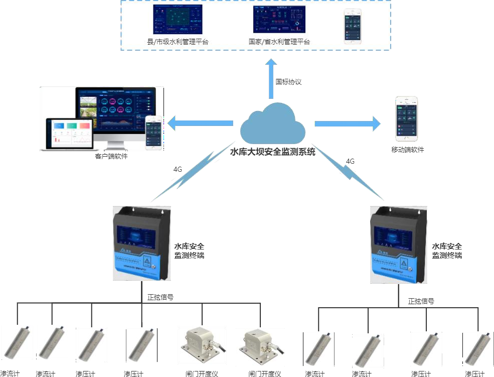
The system uses sine seepage meter, osmometer and gate opening meter sensors to collect real-time seepage flow, seepage pressure, water level and other parameters of the reservoir and transmit them to the reservoir safety monitoring terminal EMCU through sine signals for data analysis and storage. After edge computing, the effective data will be reported to the dam safety monitoring management platform through 4G mode, and transmitted to the provincial water conservancy supervision platform at the same time, and the alarm information will be pushed in time if the abnormality exceeds the standard, It is convenient for the operation and maintenance managers to maintain the safety of the reservoir dam, help the Water Conservancy Bureau to effectively manage the dynamic information of the reservoir, and make the reservoir dam more convenient to manage and safer.
3、 Hardware parameters
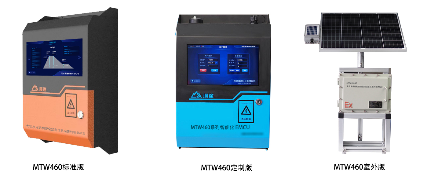
MTW460SI safety monitoring information acquisition terminal
1.1 Product introduction
The MTW460SI safety monitoring information acquisition terminal provides 16 sinusoidal interfaces, 1 RS485 interface, 2 4~20mA analog quantity, and 2 relay control interfaces, and supports simultaneous access to multiple sinusoidal sensors, analog quantity sensors, and RS485 sensors. Through 4G or network port networking, real-time data collection and upload to the network server can be realized, and remote monitoring on the platform side can be realized. It is mainly used in reservoir structure safety monitoring scenarios, which can be customized according to the actual application scenarios of customers to meet their customized needs.
1.2 Display screen interface
2. Seepage monitoring
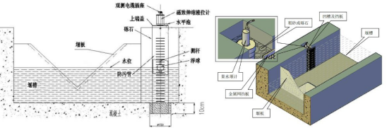
2.1 Monitoring principle
One water level gauge is set at the upstream water inlet. Three monitoring sections are selected, with each section spaced at an interval of 150m. Each section is provided with 2 lifting pressure holes, and each hole is provided with 1 silicon pressure type lifting pressure gauge, and each section is provided with 1 data acquisition unit. At the same time, a triangular weir is built at the downstream dam toe. The seepage flow is observed by measuring weir, which is arranged on the side wall of the drainage channel. Weir plate is required for embedded installation. The instrument is located 1 m away from the upstream of the weir plate. A groove is opened on the side wall of the weir groove at the installation location. After the instrument is fixed, gravel is placed in the groove to filter water.
2.2 Point layout
Generally, it is set on the straight section of the water collecting ditch. The upstream and downstream ditch bottoms and slopes need to be protected to avoid water leakage. A special concrete or masonry water channel can be built. The designed weir water depth is lower than the weir mouth, causing free overflow at the weir mouth. In order to obtain accurate observation results, the weir wall shall be perpendicular to the water diversion channel and the incoming direction and vertical. The weir plate is made of stainless steel plate, the surface shall be flat and smooth, and the weir mouth shall be made into a 45 ° angle close to the downstream edge. The water gauge of the measuring weir shall be set at the upstream of the weir mouth, the distance from the weir mouth shall be 3~5 times the weir head, and the water gauge variation shall be 0.1 mn. In order to stabilize the upstream flow of the measuring weir, a flow stabilizing device can be installed at the upstream of the water gauge.
3. Osmotic pressure monitoring
3.1 Design principle
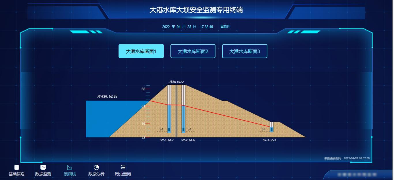
Monitoring of dam body phreatic line: select 3 observation sections, arrange 2 piezometers from the dam crest to the downstream dam slope in each section, observe the water level in the piezometers, and draw the phreatic surface. The method is intuitive and clear.

The method of borehole burying shall be adopted for burying the osmometer, and the borehole diameter is about ¢ 80~100mm. The depth of the borehole shall be more than 40cm deeper than the designed burial elevation of the osmometer. After the hole is formed, coarse sand shall be poured into the hole bottom, and sand shall be placed in the permeable cloth to make sand to wrap the osmometer and put it into the hole to lay medium fine sand. After the osmometer is installed in place, the initial value of the osmometer shall be measured in time, and records shall be made and filed according to the number of the osmometer and the design number. The outgoing cable of the osmometer shall be strictly protected.
4、 System functions
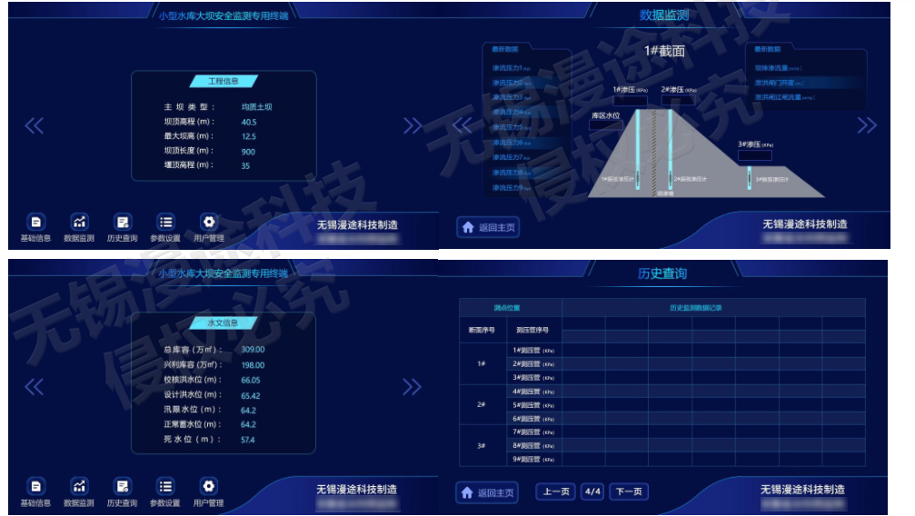
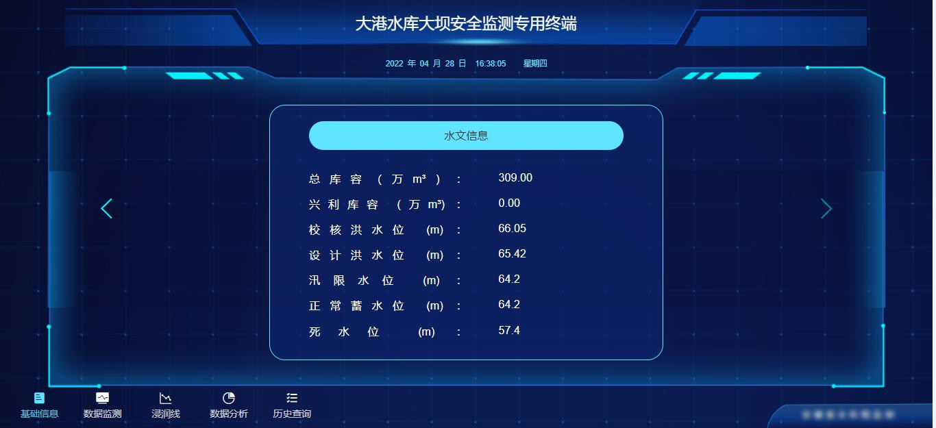
Basic information: real-time display of basic parameter information of the current dam, synchronization of local terminal data, including reservoir capacity, water level and other information;
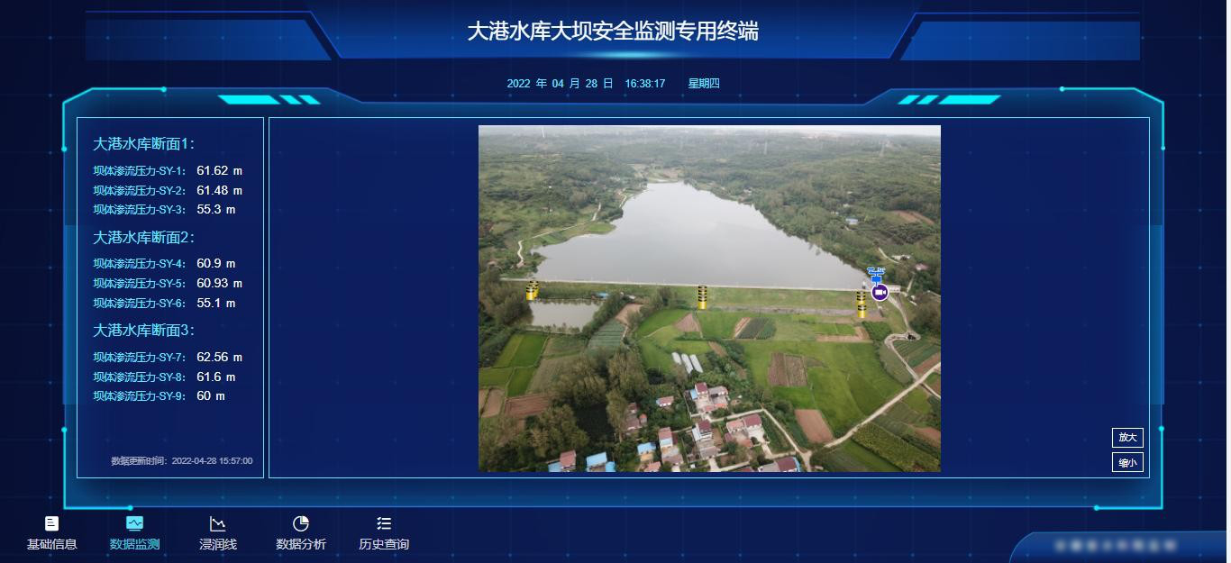
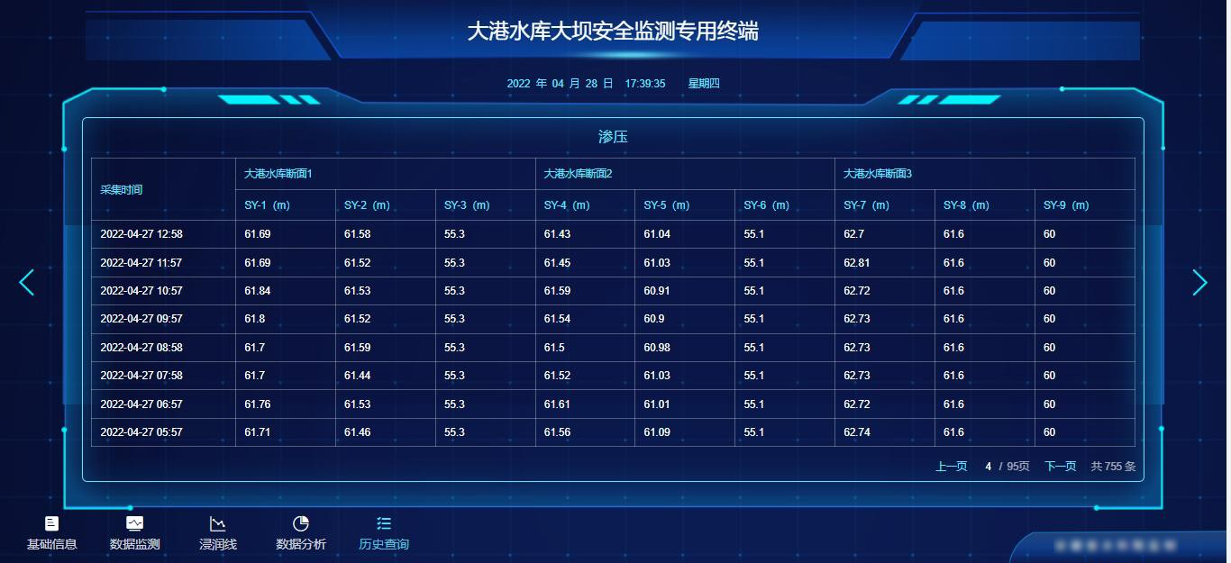
Data monitoring: real-time display of seepage pressure, seepage pressure, water level and other information of the reservoir section, and real-time update display according to sensor monitoring data;
Phreatic line: real-time display of the current reservoir water level, pressure surface pressure, seepage flow and other information at each monitoring point of the section;
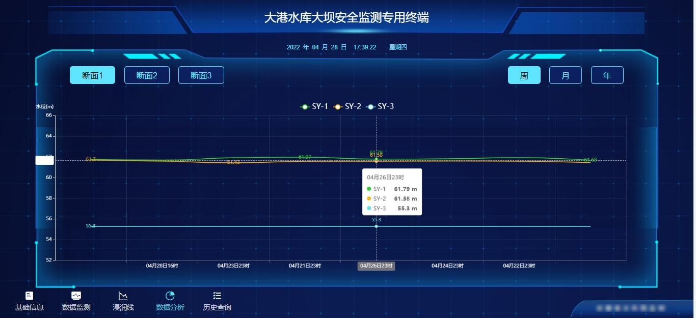
 Data analysis: the real-time monitoring data will automatically form an analysis line chart, which is conducive to intuitive analysis of the reservoir dam safety coefficient according to the trend trend, so as to make timely response measures to prevent dam collapse;
Historical data: support query of water level, seepage pressure and other parameters of the dam in different periods of time, and support export and backup of historical data.
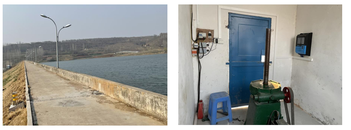
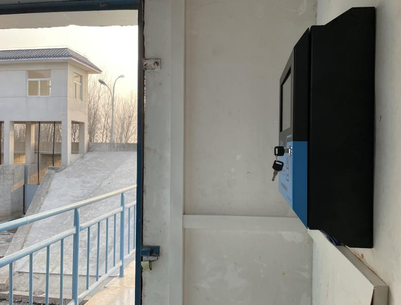
5、 Project site
hotline:400-6822950
Email:service@mantoo.com.cn